Typically, the trend in power converters is to use larger and larger semiconductor switches (IGBTs) instead of paralleling many small. The demonstrator shows a powerstack built up of smaller IGBT modules than the “typical” wind power modules, the PrimePack3.
With a basic powerstack design built up around the PrimePack3 a typical DFIG configuration for 2 and 3 MW will be as below:
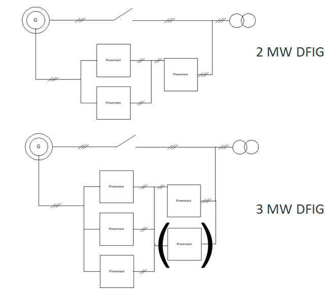
Figure 1 Typical DFIG converter layout with PrimePack3 based Power Modules
It is seen that the grid side is very small compared to the generator side. Some of the challenges for the DFIG converter are (not limited to DFIG):
Challenges for Generator Inverter:
- More than 2x current compared to grid inverter
- Low frequency operation 0-10 Hz - > Thermal cycling
- Diode loaded more than IGBT.
- High over-current during FRT
Challenges for Grid Inverter:
- Over-current due to overspeed /FRT
- Large grid reactor (relatively)
Large grid reactor (relatively)In order to attack most of the above challenges we have “divided” the PrimePack3 and replaced with two smaller powermodules, as shown in the below image.
Figure 2 “Cut one PrimePack into two halves” by the use of EconoDual packages instead.
The change from one PrimePack3 to two EconoDual packages not only reduces the component cost (due to higher volume), but also allows for a more innovative control method named “Discontinuous interleaving”.
A three phase inverter stack is built up as a demonstrator.
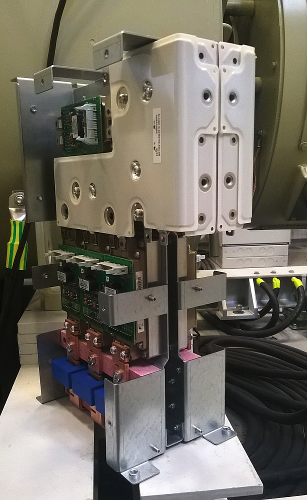
Figure 3 2x 3 phase inverter designed for discontinuous interleaving
The discontinuous interleaving principle has the following properties:
- Virtually remove diode reverse recovery losses and associated IGBT turn-on losses
- Slightly increase of conduction losses
Loss measurement comparisons
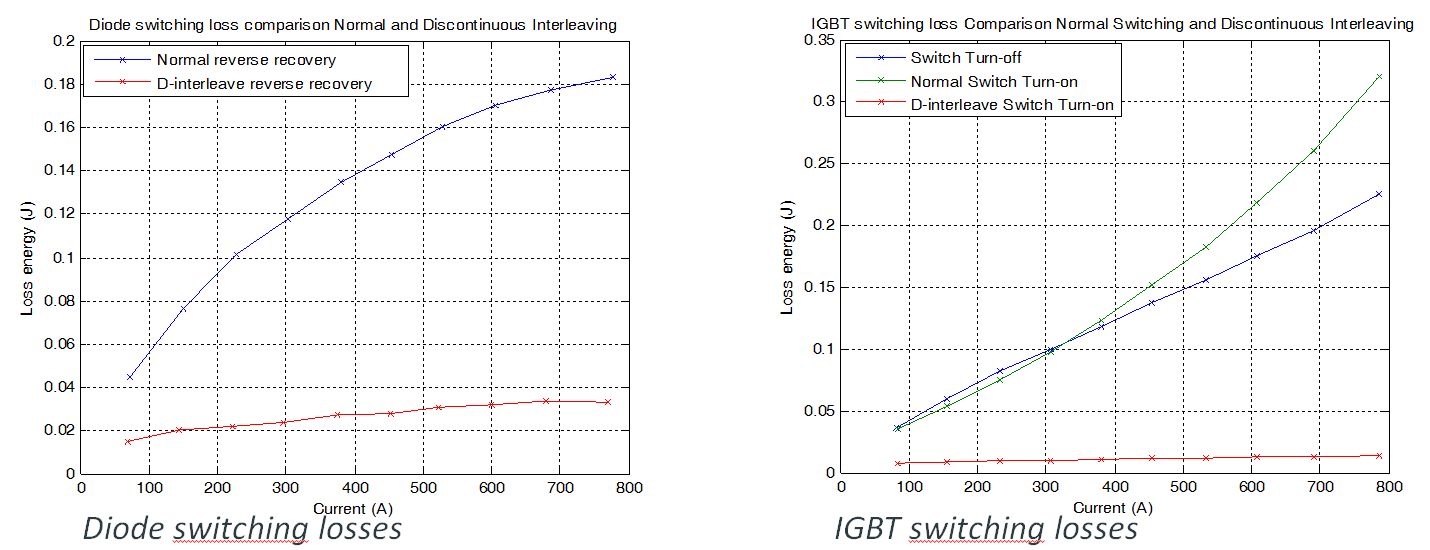
Figure 4 Double Pulse Test results comparing normal switching (direct parallel) and D-interleaving
Also thermal testing of direct paralleling (typical switching pattern) and discontinuous interleaving is done, shown below.
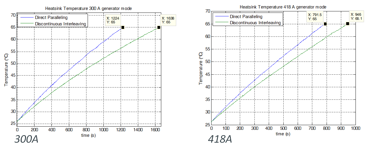
Figure 5 Thermal Comparison of direct paralleling vs discontinuous interleaving
The thermal tests show that the total powermodule losses are reduced by running discontinuous losses. The results are:
D-interleaving losses compared to Direct paralleling
• 75% @ 300 A
• 84% @ 418 A
Conclusion
A powerstack/control method which reduces the powerlosses in standard IGBT modules has been demonstrated.
The reduction in losses will allow for higher current rating (powerdensity) and/or more robustness/lifetime. In total a cost and size benefit for the DFIG converter.