TRIPLE PULSE TESTER FOR POWER LOSS CHARACTERIZATION

The test setup is partially sponsored by The Obel Family Foundation and is the world's first of its kind.
Figure 1 presents a picture of the rack-mounted setup.
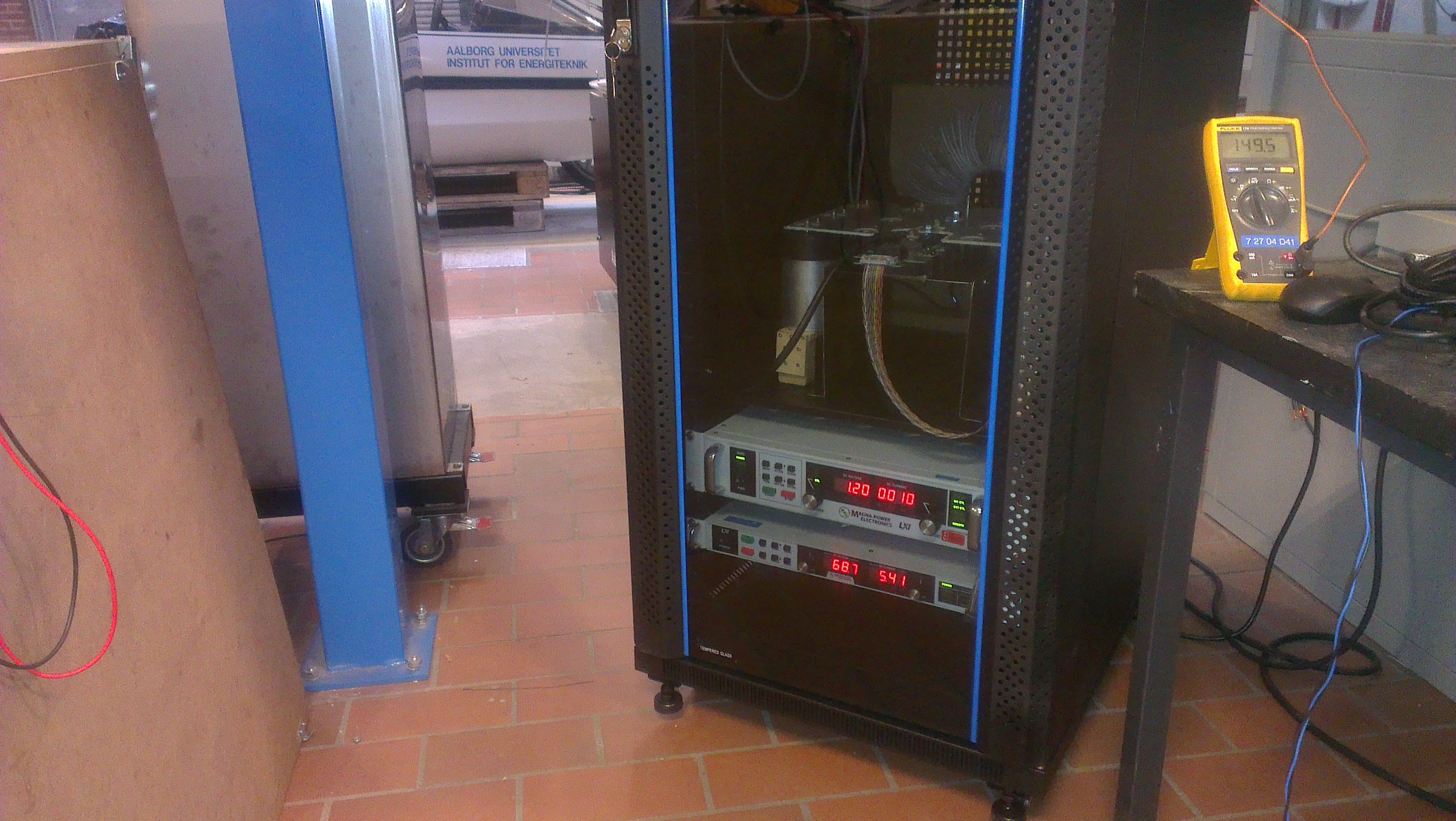
FIGURE 1: THE RACK-MOUNTED TEST SYSTEM
The high-level control of the system is implemented using LabView and is fully automated. A DSP will handle the low-level control of the IGBTs. The system output will be a series of conduction loss measurements and switching loss measurements at the different temperature levels, current levels and voltage levels.
The test setup utilizes the on-state voltage measurement enabled gate driver developed during the IEPE project to obtain the conduction losses in the module, see Figure 2. Therefore, by using the IEPE gate driver that can measure the on-state voltage drop of transistors and diodes when they are in conduction, a full loss characterization of a power module is possible to be done a single test setup.
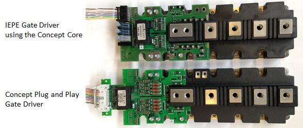
Figure 2: IEPE Gate Driver with on-state voltage drop measurement based on the Concept Driver Core
Characterization of both standard and new prototype IGBT power modules can be obtained using the setup. This can include modules with Si diodes or hybrid modules with Si IGBTs and SiC diodes.
Besides characterizing of IGBT modules the setup can also be used for short-circuit testing of both IGBTs and gate drives. In Figure 2, a schematic of the complete setup is presented.
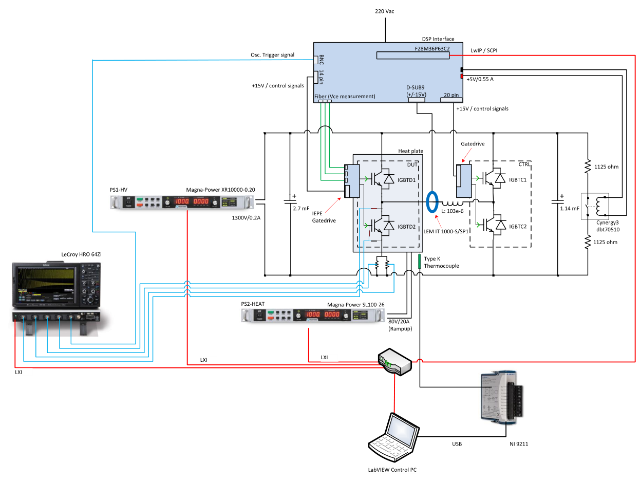
Figure 3: Test setup schematic
As seen on the figure above the system consists of an H-bridge connected to a 103 uH inductor. On the left leg of the H-bridge, the DUT IGBT is mounted and on the right leg, a control IGBT is mounted. A LEM current sensor in combination with the collector-emitter voltage measurement enabled gate driver provides the means for measuring conduction losses.
A LeCroy oscilloscope measures the switching losses in the IGBT. The Magna-Power XR10000-0.20 power supply provides power for charging the DC-link capacitors and the Magna-Power SL100-26 provides power to the heat plate. The LabVIEW control pc regulates the temperature of the heat plate and controls the test sequence.
Table 1: Ratings of the main components
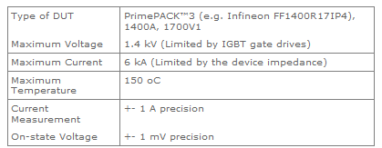
1. Limited by the available manufactured bus bar. For DUTs with different layout, the DUT bus bar must be redesigned.
Objective and Research Content
Measurement of on-state voltages
On-state voltage measurement with high precision is realized with synchronous sampling of the device current. Therefore the resulting measurements can be used as means of calibration for estimation of the devices junction temperature. Such measured characteristics can be seen in Figure 4.
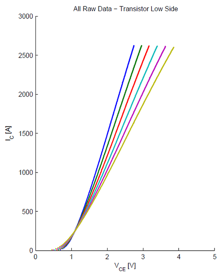
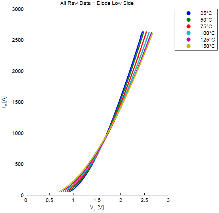
Figure 4: On-state voltage measurement: (left) IGBT, (right) diode
Measurement of switching losses
Synchronous measurements of current and voltage are done using a 12-bit Oscilloscope equipped with high bandwidth measurement probes. The switching waveforms are shown in Figure 5, while the switching energy losses at 150 oC for different blocking voltages are shown in Figure 6 and Figure 7.

Typical Turn-ON (left)
Turn-OFF (right)
Center
Figure 5: Typical Turn-ON (left), Turn-OFF (right) and Center waveforms at 125 oC
4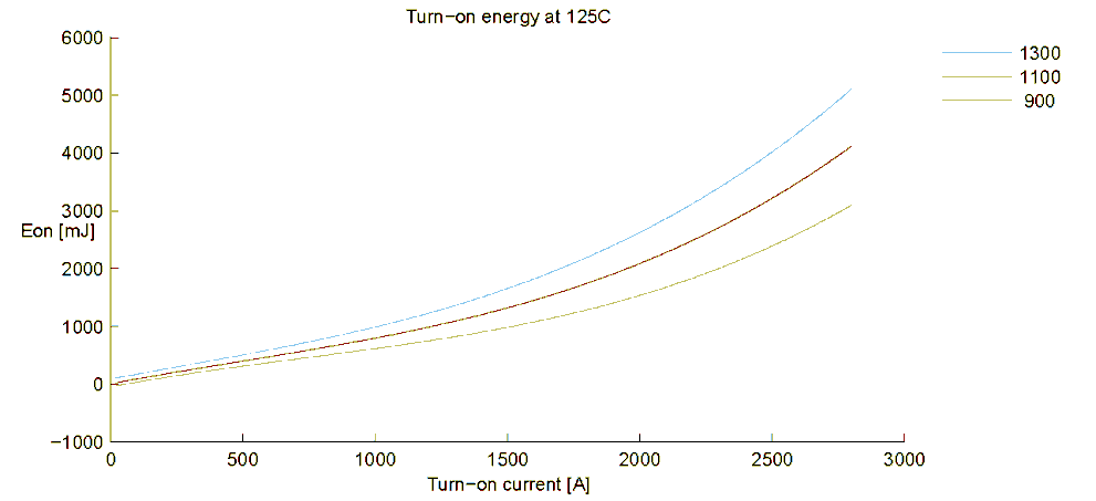
Figure 6: Turn-ON loss energy at 125 oC and 3 voltage points
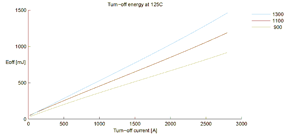
Figure 7: Turn-OFF energy loss at 125 oC and 3 voltage points
Measurement of the bus bar stray inductance
During switching, the bus bar stray inductance can be detected (e.g. ~ 7 nH) – see Figure 8
Figure 8: Estimation of bus-bar stray inductance during switching
4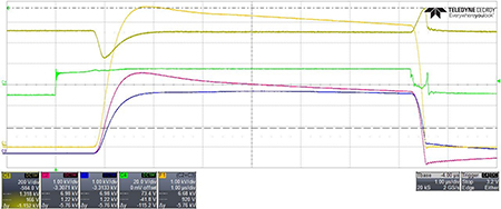
Figure 9: Short-circuit behaviour of an IGBT power module