About the 1 MVA Test Platform
This test platform is developed within the Intelligent and Efficient Power Electronics (IEPE) project, which aims to develop more intelligent and more efficient power electronics in close collaboration with industry partners.
The main components are three converter stacks in a converter cabinet, a three phase inductor, a control/monitoring interface, a power supply and two liquid cooling systems, see Figure 1.
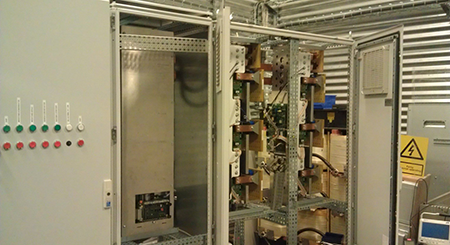
Figure 1: The 1 MVA Test Platform
The High Power IGBT modules are fundamental power semiconductor devices in a wind turbine. These devices are mounted in the converter power stacks. This operation modes and test conditions are applied for the device under test (DUT) power stack, conditions created using other two paralleled converters (Control 1,2) that will control the inductor current, see Figure 2.
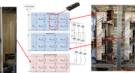
Figure 2: The 1 MVA Test Platform Power Schematic
The monitoring interface is installed in all the High Power IGBT modules. The monitoring interface allows measuring the collector emitter voltage VCE of all IGBTs and the forward voltage of the all the antiparallel diodes VF during converter operation.
These parameters have been used as a wear out indicator previously. The novelty that offers the online monitoring interface is the possibility of precisely measuring these temperature sensitive electrical parameters (TSEP) as VCE and VF, which in addition to the current monitoring allows the estimation of the junction temperature of the power modules.
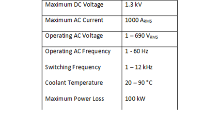
Table 1: Ratings of the main components
Objective and Research Content
Power Density
Measurement of on-state voltages is realized during the converter operation as can be seen in Figure 3.
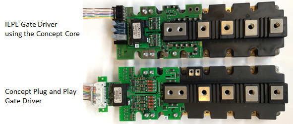
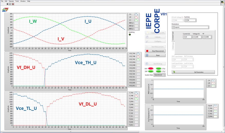
Figure 3: IEPE Gatedrive and On-state voltage measurement for all devices of phase U in DUT during operation
The test platform has been designed to test the power stacks to their limits, which allows the test and verification of converters power density. The present power stacks were initially designed for wind turbine operating at 690V and 500A, and the aim is to double the power density (1000A).
Example of such power limit investigation is shown in Figure 4, where based on junction temperature feedback from the IGBTs and diodes – the power transfer limit ca be detected. The particular example in Figure 4 is in the case of switching 1070 VDC, and using a cooling temperature up to 60 grades C.
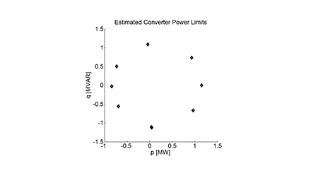
Figure 4: The 1 MVA Stack Under Test (DUT) Power Limits at 150 grades C Tj,max
Reliability
Lifetime testing can be performed using a predefined load profile, where the reliability of the converter under test can be measured. Feedback of the on-state voltage measurement can be used to detect the end of life, and stop the converter operation before it is physically damaged.