There is no doubt that WBG (Wide Band Gap) devices are the next generation of semiconductors in power electronics. As power semiconductors for industrial drives, WBG devices are still at the beginning due to very large cost and limited field experience.
SiC MOSFET is considered a drop-in replacement for Si MOSFET and IGBT in the existing designs meaning it can be used in actual drives with very little circuit modifications. Therefore fast prototyping is possible and by that, acquiring practical experience is achievable in short time.
Prototype drive
A 15kW/500V prototype drive was built (see Figure 1) from a standard drive with module from Danfoss Silicon Power having full SiC inverter. This means that the inverter Si IGBTs are replaced with SiC MOSFETs and the inverter FWDs (Free Wheeling Diode) are replaced with SiC diodes.
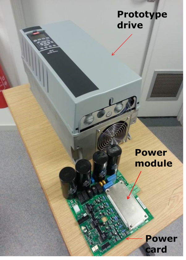
Figure 1: 15kW/400V prototype drive with SiC MOSFET inverter; power card with power module mounted inside the drive
No other power components are changed compared to a standard drive with Si IGBTs inverter. The gate drive for the SiC inverter has been adapted in order to match the gate voltage levels required to optimally drive SiC MOSFETs.
The gate resistance for the SiC inverter has been chosen such as to avoid in first place the use of an external output filter in order to protect the motor against high dv/dt (only the motor cable length will attenuate the dv/dt). The efficiency comparison of SiC-drive vs. Si-drive is made easier by not including the output filter in the measurements.
Power module
A schematic and pictures of the power modules assembly, SiC inverter on the left and standard Si inverter on the right are shown in Figure 2. For faster prototyping the replacement of the Si IGBTs was made without modifying the layout of the existent module.
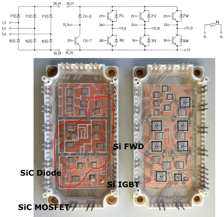
Figure 2: Power module schematic (top) and internal layout (bottom); SiC inverter (bottom-left) and standard Si inverter (bottom-right)
Drive efficiency
The comparison of the drives efficiency measured at different output powers and switching frequencies shows the superiority of the SiC inverter vs. Si inverter at high switching frequencies, see Figure 3. The efficiency of the drive with Si IGBTs is shown on the top while the efficiency of the drive with SiC MOSFETs, in same conditions, is shown on the bottom.
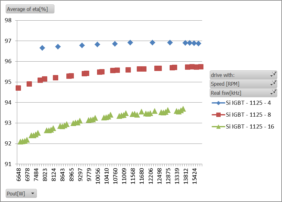
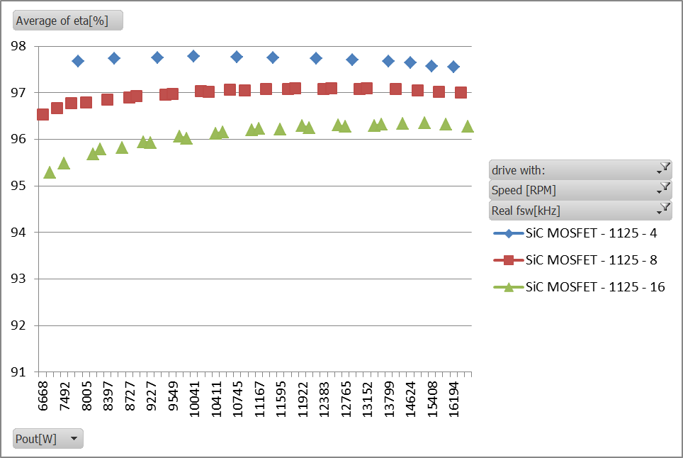
Figure 3: Drive efficiency at different output power levels and switching frequencies; standard Si inverter (top), SiC inverter (bottom)
Another advantage of using MOSFETs for the inverter is that it keeps the efficiency curve “flat” at all power levels due to linear loss dependency vs. load current of the MOSFET. This can also been observed in Figure 3.
As future work further optimization related to switching speed of SiC inverter, in order to increase the efficiency, is to be conducted in coordination with development of an output filter. EMI performance of the SiC drive with and without and output filter is also to be investigated.
Contact Person
Marian Lungeanu
Senior Engineer
Converter Design, Department DDS-RDHW/DK
E-mail: marian.lungeanu@danfoss.com