The reliability of high power converter is mired by stressors such as temperature, humidity, mechanical vibration, etc. Especially, power modules are stressed by electrical parameter such as current, voltage, and frequency because of high power density and firmed packaging to reduce the cost and overall size of the converter. Accelerated test set up (ATS) is built to emulate real life stressors into test devices, here high power IGBT module is used as a test device. The ATS is featured with locally built smart monitoring abilities for temperature sensitive electrical parameter, temperature etc. in real time while the converter is in operation. The outcome can be used to improve converter design, packaging of components, and study overall reliability of power converter. The test set up can also be used to generate degradation and lifetime model of high power IGBT modules.
The test setup is connected to CORPE (Center of Reliable Power Electronics) which you can read more about here.
About Accelerated Test Setup
Two types of accelerated tests are normally used: active thermal cycling/ power cycling (A-TC) and passive thermal cycling (P-TC). A-TC is a common approach for evaluation design and performance under a given loading, as well as end of life tests at accelerated conditions. In A-TC setups the device under test (DUT) is heated through sheer conduction losses. However to get closer to real world stresses the DUT in proposed ATS handled as an active component and switched under normal working conditions using AC cycling. The proposed test method is categorized as an advanced A-TC method as demonstrated in Fig.1.
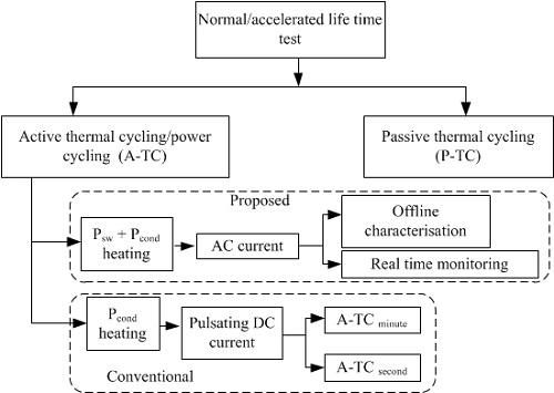
Figure 1. Proposed ATS in context with conventional test methods
Block Diagram of ATS
A block diagram of ATS is shown in Fig. 2.
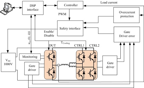
Figure 2. Block diagram of the proposed ATS
ATS
Some related pictures for the ATS are demonstrated in Figs. 3, 4, and 5.
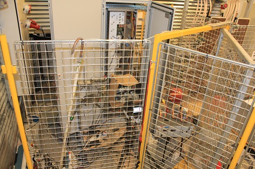
Figure 3. ATS inside a cage
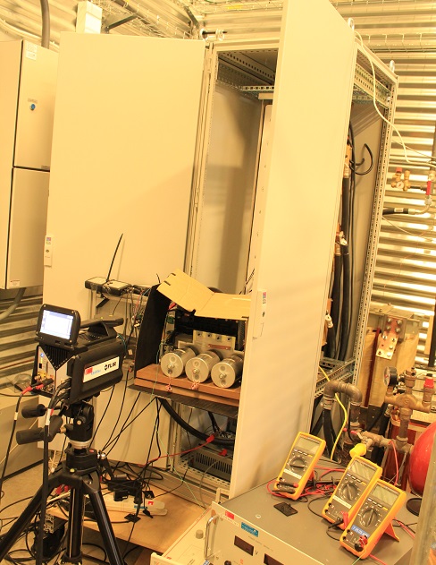
Figure 4. ATS under open module test using Infra Red camera for direct Tj measurement
ATS Features
Major features of proposed ATS are highlighted below.
- Characterization of IGBT and free-wheeling diode (FRD) at reted power in converter itself.
- Real time monitoring of on-state collector emitter voltage drop (Vce) of IGBT and forward voltage (VFD)of corresponding FRD in converter operation.
- Real time average junction temperature estimation.
- Direct junction temperature measurement using high resolution infra red camera on open module under normal working condition.
- Ageing and lifetime investigations of power module.
Objectives and Research Content
1. Develop and build real time monitoring of temperature sensitive electrical parameter (TSEP) such as on-state voltage drop, including current and temperature. The charaterization of low side IGBT and coreesponding FRD in a half bridge module (1700V, 1000A) are shown in Figs. 5 and 6. Similarly, real time monitoring of on-state Vce and VFD are shown in Fig. 7. The electrical parameters for these parameters are tabulated in Table 1.
Table1: Stressed paramter for ageing test of power module
| DC link voltage | 1000V |
| Load current | 650Arms |
| Output frequency Switching frequency |
6Hz 2.5kHz |
| Cooling tempertaure | 80oC |
| Cooling | Water mixed with glycol |
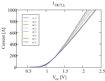
Figure 5. IV characterization of IGBT
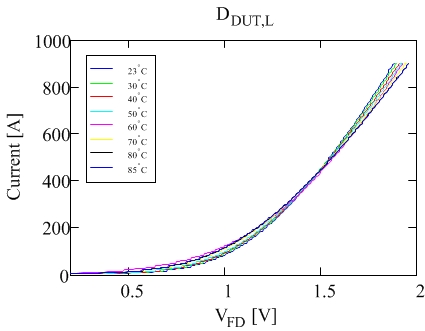
Figure 6. IV characterization of diode
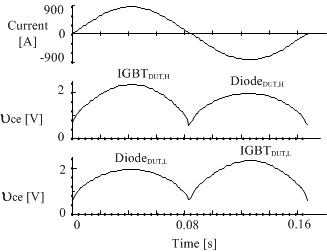
Figure 7. Online measurement of Vce and VFD
2. Estimation of stressors such as junction tempertaure (Tj) of power module in converter operation.
Figs. 8 and 9 shows direct tmpertaure measurement of open module in normal sinusoidal current loading in IGBT and FRD. Fig. 8 shows IR image measured when IGBT is conducting (left) and when FRD is conducting (right) on high side of a half bridge module.
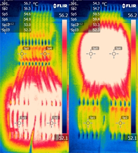
Figure 8. IR measurement of open module for: (left) IGBT is conducting and (right)diode is conducting
Similarly, Fig. 9 shows Tj variation at Sp1 on IGBT, Sp5 on diode and on copper surface (Sp12 and Sp13). The Tj is measured at DC link voltage: 450V, sinusoidal current: 115Apeak, frequency: 6Hz, and baseplate tempertaure at 50oC.
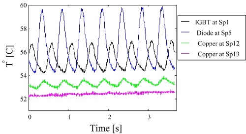
Figure 9. Tj variation on IGBT, FRD and on copper surface as pointed in Fig. 8
This video shows direct measurement of temperature variation at 400 fps for above measurement.
3. Ageing and health monitoring of power modules.
Fig. 10. shows on-state VFD evolution on low side FRD after certain cycles of operation. PM1 run for 5.1 million cycle until it fails. Similarly, PM2, PM3 and PM4 run for 4.5, 3.5 and 2.5 million cycles and stopped delibarately to study degradation mechainms and physics of falures of power modules. All power modules are stressed under similar loading conditions as tabulated in Table 1.
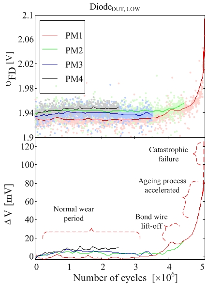
Figure 10. On-state voltage evolution during ageing test of power modules
Publications
Some selected publications are listed below.
1. Real time wear-out monitoring test setup for high power IGBT modules, submitted.
2. Improving Power Converter Reliability: Online Monitoring of High-Power IGBT Modules. / Ghimire, Pramod; de Vega, Angel Ruiz; Beczkowski, Szymon; Rannestad, Bjørn; Munk-Nielsen, Stig; Thøgersen, Paul. In: I E E E Industrial Electronics Magazine, Vol. 8, No. 3, 09.2014, p. 40-50.
3. A real time measurement of junction temperature variation in high power IGBT modules for wind power converter application. / Ghimire, Pramod; Pedersen, Kristian Bonderup; de Vega, Angel Ruiz; Rannestad, Bjørn; Munk-Nielsen, Stig; Thøgersen, Paul Bach.
Integrated Power Systems (CIPS), 2014 8th International Conference on. VDE Verlag GMBH, 2014. p. 1-6 6776812.
4. An online Vce measurement and temperature estimation method for high power IGBT module in normal PWM operation. / Ghimire, Pramod; de Vega, Angel Ruiz; Beczkowski, Szymon; Munk-Nielsen, Stig; Rannested, Bjørn; Thøgersen, Paul Bach.
Proceedings of the International Power Electronics Conference (IPEC-Hiroshima 2014 - ECCE-ASIA). IEEE Press, 2014. p. 2850 - 2855.
5. Online Vce measurement method for wear-out monitoring of high power IGBT modules. / Beczkowski, Szymon; Ghimire, Pramod; de Vega, Angel Ruiz; Munk-Nielsen, Stig; Rannestad, Bjørn; Thøgersen, Paul.
Proceedings of the 15th European Conference on Power Electronics and Applications, EPE 2013. IEEE Press, 2013.
6. A review on real time physical measurement techniques and their attempt to predict wear-out status of IGBT. / Ghimire, Pramod; Beczkowski, Szymon; Munk-Nielsen, Stig; Rannestad, Bjørn; Thøgersen, Paul Bach.
Proceedings of the 15th European Conference on Power Electronics and Applications, EPE 2013. IEEE Press, 2013.